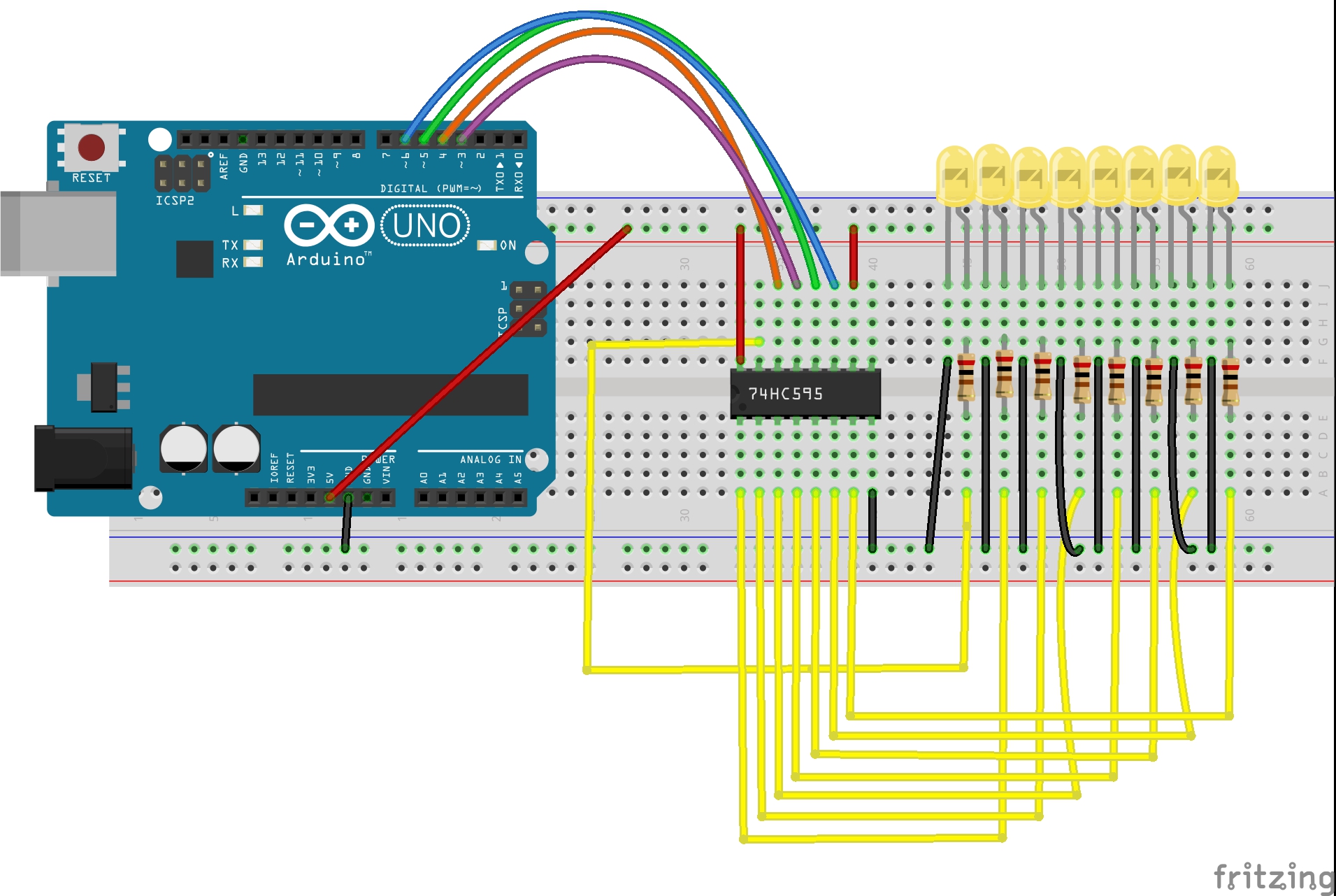
LED Brightness Control Using Potentiometer Code/sketch /*Īrduino Tutorial #7 - LED Brightness Control Using Potentiometer LED Brightness Control Using Potentiometer Circuit diagram / Schematic LED Brightness Control Using Potentiometer Circuit Diagram Circuit Wiring Components PinsĬonnected to Arduino Digital pin “D5” through a 220-ohm resistor.

Re-maps a number from one range to another.
#Arduino led brightness control code#
LED Brightness Control Potentiometer Input vs LED Output Voltage Graph What is the map( ) Function in Arduino Code

The LED brightness changes Low to High according to the change of PWM output value 0 to 255. Where the value “0” represents “0 volts” and 255 represents “5 volts”. This pin provides analog results with digital means at the range of 0 to 255. Potentiometer Internal Construction and Symbol Digital output on the LEDĪnother side, the positive terminal of the LED connected to the PWM(Pulse Width Modulation) pin. When we will Rotate the potentiometer knob, then the output voltage is change and the Arduino reads this changing of output voltage as the input voltage. Where the value “0” represents “0 volts” and the value “1023” represents “5 volts”. Arduino analog pin has 10-bit Analog to Digital Converter(ADC), which converts the potentiometer output voltage into integer value between the range of 0 to 1023 volts (2^10 = 1024) as input. Now we can read the output from terminal 2 of the potentiometer, and we need to connect this terminal to an analog pin of the Arduino board. First of all, we need to connect the Potentiometer terminal 1 is connected to +5v Vcc, and terminal 3 is connected to the ground.


 0 kommentar(er)
